")
Powering Precision: Advanced Switchgear & Substation Drawings Using Electrical CADD
The modern electrical landscape demands accuracy, speed, and seamless coordination across every stage of infrastructure development. Electrical Switchgear CADD Drawings play a central role in ensuring stable power distribution, yet their design process can become highly complex without the right tools. As projects scale in size and technical requirements increase, traditional drafting methods often fall short of delivering the precision required for today’s engineering standards.
Electrical Switchgear CADD Drawings
Electrical CADD (Computer-Aided Design and Drafting) has emerged as a transformative solution, enabling engineers to design, document, and manage electrical systems with exceptional clarity and efficiency. By leveraging digital tools, professionals can create highly detailed switchgear and substation drawings that reduce errors, improve productivity, and enhance collaboration. This blog provides a comprehensive exploration of how Electrical CADD is applied in switchgear and substation drawings, covering concepts, workflows, best practices, and future trends in a structured and reader-friendly manner.
1. Fundamentals of Switchgear Systems in Electrical Design
Electrical Switchgear CADD Drawings for controlling, protecting, and isolating electrical equipment. They ensure that power systems operate safely under both normal and fault conditions. These systems include circuit breakers, relays, isolators, and fuses, each designed to perform a specific function within the electrical network.
When designing switchgear systems, engineers must ensure that every component is properly represented in the drawings. Electrical CADD simplifies this process by providing accurate symbol libraries and scalable drawing environments. As a result, engineers can visualize system behavior and ensure proper coordination among components. This clarity not only enhances design quality but also supports efficient installation and maintenance.
2. Substation Design and Its Critical Role
Substations serve as the link between power generation and distribution. They step up or step down voltage levels and regulate the flow of electricity across networks. A well-designed substation ensures reliability, safety, and operational efficiency.
Electrical CADD enables designers to create detailed substation layouts that account for equipment positioning, electrical connections, and safety clearances. It allows engineers to simulate real-world conditions and identify potential issues early in the design phase. Consequently, project risks are minimized, and performance is optimized.
3. Why Electrical CADD Is Indispensable Today
In an era driven by digital transformation, Electrical CADD has become a fundamental tool for electrical engineers. Unlike manual drafting, CADD offers precision, flexibility, and speed. Designers can quickly modify drawings, reuse templates, and maintain consistency across multiple projects.
Moreover, Electrical CADD enhances collaboration by enabling teams to share and review designs in real time. This reduces communication gaps and ensures that all stakeholders remain aligned throughout the project lifecycle. As a result, project delivery becomes faster and more efficient.
4. Core Elements of Switchgear Drawings
Electrical Switchgear CADD Drawings provide a detailed representation of electrical control and protection systems. These drawings are crucial for understanding system functionality and ensuring proper installation.
They typically include several important elements:
- Single Line Diagrams (SLDs) that represent the overall system structure
- Control schematics that illustrate operational logic
Each element must be designed with precision and clarity. Electrical CADD tools help maintain uniformity by offering standardized symbols and automated drafting features, making it easier to produce professional-grade drawings.
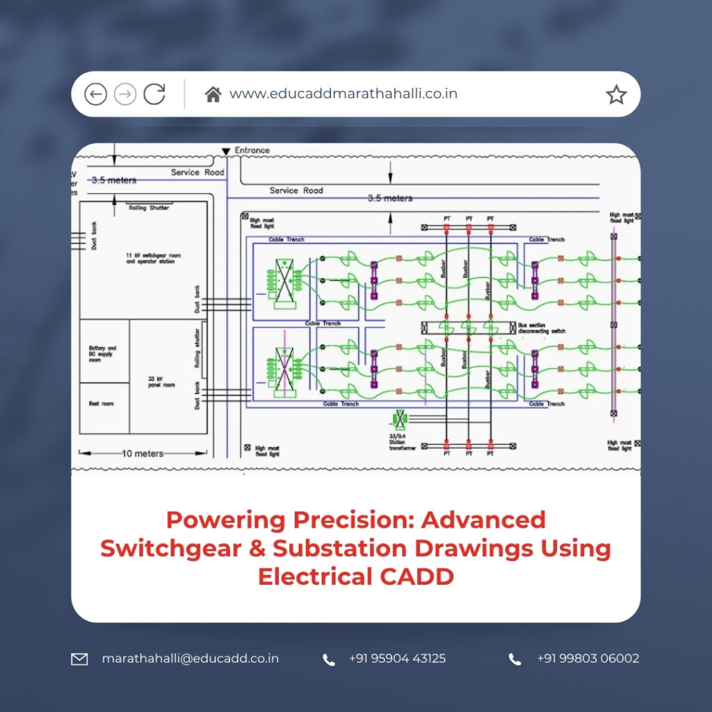
5. Essential Components of Substation Drawings
Substation drawings are more comprehensive and require careful attention to detail. They include layouts for transformers, busbars, feeders, and grounding systems, among other components.
Designers must ensure that all elements are accurately positioned and interconnected. Electrical CADD provides the tools needed to create detailed and scalable layouts, allowing engineers to visualize the entire system before construction begins. This proactive approach helps in identifying design flaws and optimizing performance.
6. Types of Electrical Drawings Used in CADD
Electrical CADD supports a variety of drawing types, each serving a specific purpose in the design process. These drawings collectively provide a complete view of the electrical system.
Common types include general arrangement drawings, wiring diagrams, and cable schedules. Each drawing contributes to a deeper understanding of system functionality. By integrating these drawings within a single platform, Electrical CADD ensures consistency and improves workflow efficiency.
7. Advantages of Using Electrical CADD in Engineering Projects
Electrical CADD offers numerous advantages that make it an essential tool in modern engineering. It significantly improves design accuracy while reducing the time required for drafting and revisions.
Some notable benefits include:
- Enhanced design precision with minimal errors
- Faster project completion through automation
In addition, Electrical CADD supports better documentation and compliance with industry standards. This ensures that projects meet regulatory requirements and client expectations.
8. Step-by-Step Workflow for Switchgear Drawings
Creating switchgear drawings involves a structured workflow that ensures accuracy and completeness. The process begins with gathering project requirements and understanding system specifications.
Next, engineers develop preliminary layouts and select appropriate components. Electrical CADD tools then assist in drafting detailed diagrams and refining designs. Throughout the process, designers can easily make changes and updates, ensuring that the final output meets all technical requirements.
9. Designing Efficient Substation Layouts
Substation layout design is a critical aspect of electrical engineering. It requires careful planning to ensure optimal equipment placement and safe operation.
Electrical CADD allows designers to create precise layouts that consider spatial constraints and safety standards. It also enables easy modifications, which is essential during the design phase. By using CADD tools, engineers can optimize layouts for both performance and cost-effectiveness.
10. Importance of Standards and Compliance
Adhering to industry standards is essential for creating reliable and safe electrical designs. Standards ensure that drawings are consistent, easy to interpret, and compliant with regulations.
Electrical CADD tools incorporate standardized symbols and templates, making it easier to follow established guidelines. This reduces errors and improves communication among project teams. As a result, projects are executed more smoothly and efficiently.
11. Overcoming Challenges in Electrical CADD
While Electrical CADD offers many benefits, it also presents certain challenges. These may include software complexity, data management issues, and coordination difficulties.
However, these challenges can be addressed through proper training and effective workflow management. By adopting best practices and using standardized templates, designers can minimize errors and improve efficiency. Continuous learning and adaptation are key to overcoming these obstacles.
12. Integration with Advanced Engineering Technologies
Electrical CADD is often integrated with other advanced technologies such as Building Information Modeling (BIM) and simulation tools. This integration enhances design accuracy and project coordination.
By combining CADD with these technologies, engineers can create more detailed and interactive models. This allows for better visualization and analysis of electrical systems. As a result, decision-making becomes more informed and effective.
13. Best Practices for Creating High-Quality Drawings
To produce high-quality electrical drawings, designers must follow established best practices. These practices ensure clarity, accuracy, and consistency across all documents.
Key practices include maintaining proper layering, using clear labeling, and conducting regular design reviews. Additionally, version control should be implemented to track changes and avoid confusion. By following these guidelines, designers can create professional and reliable drawings.
14. Future Scope of Electrical CADD in Power Systems
The future of Electrical CADD is shaped by advancements in technology and increasing demand for efficient power systems. Automation, artificial intelligence, and cloud-based solutions are transforming the design process.
These innovations enable faster and more accurate designs while improving collaboration among teams. As the power industry continues to evolve, Electrical CADD will remain a vital tool for engineers. Those who embrace these advancements will be well-positioned to lead the next generation of electrical design.
Conclusion
Electrical Switchgear CADD Drawings are at the heart of modern electrical infrastructure. Their accuracy and clarity directly impact the performance and safety of power systems. Electrical CADD has revolutionized the way these drawings are created, offering unmatched precision, efficiency, and flexibility.
By adopting Electrical CADD, engineers can streamline their workflows, reduce errors, and deliver high-quality designs that meet industry standards. From conceptual planning to final documentation, CADD tools play a crucial role in every stage of the design process. As technology continues to advance, mastering Electrical CADD will not only enhance professional capabilities but also contribute to the development of smarter and more reliable power systems.

