")
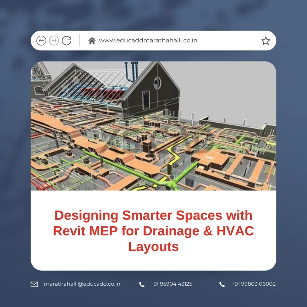
Designing Smarter Spaces with Revit MEP for Drainage & HVAC Layouts
Modern construction projects demand precision, efficiency, and seamless coordination between different building services. Mechanical, Electrical, and Plumbing (MEP) systems play a vital role in ensuring comfort, functionality, and sustainability within structures. When it comes to planning drainage and HVAC layouts, Revit MEP Design Layouts stands out as a powerful Building Information Modeling (BIM) tool.
Revit MEP Design Layouts
This blog provides a complete step-by-step guide to using Revit MEP for drainage and HVAC layouts. You will learn how it simplifies design workflows, reduces errors, and enhances collaboration between teams.
Whether you are an MEP engineer, a contractor, or a design professional, this detailed guide will help you understand the capabilities of Revit MEP for drainage and HVAC systems.
The Importance of Revit MEP in Building Design
Revit MEP offers an intelligent, model-based approach for creating precise layouts. Unlike traditional drafting, it integrates data-driven elements that adapt when modifications occur.
Why it matters:
-
Accuracy in Design: Engineers can detect clashes early, saving time and costs.
-
Realistic Visualization: Stakeholders can visualize HVAC and drainage systems before execution.
-
Improved Collaboration: All teams work on a unified model, reducing miscommunication.
-
Energy Efficiency: Smart modeling supports green building practices.
For drainage and HVAC, accuracy is crucial. Incorrect pipe sizing or duct placement can disrupt the entire building operation. Revit MEP ensures every element fits seamlessly within the design.
Setting Up Revit MEP for Drainage and HVAC Projects
Before starting layout creation, the setup phase is critical. This stage establishes project templates, standards, and essential parameters.
Step 1: Define Project Templates
A template ensures consistency across projects. It includes system families, view templates, and annotation styles tailored for MEP layouts.
Step 2: Set Levels and Grids
Accurate levels and grids provide the foundation. They help align drainage pipes and HVAC ducts with architectural and structural components.
Step 3: Import Architectural Model
Importing the architectural file into Revit allows seamless coordination. Engineers can then align their drainage and HVAC systems with walls, floors, and ceilings.
Step 4: Load Families
Families contain predefined components such as pipes, fittings, ducts, and equipment. Selecting the right families ensures the model matches real-world specifications.
Proper setup minimizes errors during later stages of design.
Step-by-Step Guide to Creating Drainage Layouts in Revit MEP
Drainage systems require careful planning to ensure smooth water flow and proper disposal. Revit MEP simplifies this process with intelligent tools.
Step 1: Create Pipe Types
Define pipe types such as PVC, cast iron, or copper. Assign materials, sizes, and system classifications for drainage.
Step 2: Place Plumbing Fixtures
Position sinks, toilets, floor drains, and other fixtures. Each fixture automatically connects to the drainage network.
Step 3: Draw Drainage Pipes
Use the piping tool to create horizontal and vertical runs. Ensure correct slope values for gravity-driven systems.
Step 4: Add Fittings and Accessories
Connect pipes with elbows, tees, and reducers. Revit automatically adjusts fittings to match pipe sizes.
Step 5: Check System Connectivity
Run a system check to confirm every fixture links to the drainage network. This step avoids missing connections during construction.
Step 6: Run Clash Detection
Revit identifies conflicts between drainage pipes and other building elements. Resolve these clashes before finalizing the model.
Through these steps, drainage design becomes systematic, accurate, and efficient.
Step-by-Step Guide to Creating HVAC Layouts in Revit MEP
HVAC systems regulate temperature, airflow, and indoor comfort. Designing HVAC layouts in Revit MEP ensures performance and energy efficiency.
Step 1: Load HVAC Equipment Families
Include air handling units (AHUs), chillers, diffusers, and ducts. Families should align with manufacturer specifications.
Step 2: Place Mechanical Equipment
Position equipment in mechanical rooms or designated areas. This placement must comply with architectural layouts.
Step 3: Create Duct Systems
Draw supply, return, and exhaust ducts. Revit allows automatic duct sizing based on airflow values.
Step 4: Add Air Terminals
Insert diffusers, grilles, and registers at desired locations. Connect them to ducts for proper air distribution.
Step 5: Define System Properties
Assign system types, flow rates, and pressure values. This step ensures the HVAC model meets project requirements.
Step 6: Analyze and Validate
Revit’s analysis tools calculate airflow and pressure losses. Engineers can fine-tune the layout for efficiency.
By following these steps, HVAC layouts become both functional and optimized for energy savings.
Collaboration and Documentation with Revit MEP
Design is only one part of the process. Effective collaboration and documentation ensure successful project delivery.
Coordinated Models
Revit MEP integrates drainage and HVAC with electrical and structural models. This coordination minimizes design conflicts.
Detailed Drawings
Generate sections, elevations, and schedules directly from the model. These documents remain updated with every design change.
Construction Documents
Revit produces fabrication-ready documents, ensuring contractors can execute installations accurately.
Team Collaboration
Cloud-based collaboration allows multiple users to work on the same project simultaneously. This improves productivity and eliminates delays.
Collaboration and documentation strengthen project outcomes and client satisfaction.
Future of Drainage and HVAC Design with Revit MEP
The future of building design is digital. Revit MEP is evolving with automation, artificial intelligence, and cloud integration.
-
Automation: Smart tools reduce manual drafting.
-
Data Integration: Real-time data ensures better decision-making.
-
Sustainability: Energy analysis supports eco-friendly designs.
-
Cloud Workflows: Remote collaboration speeds up delivery.
Adopting Revit MEP now prepares engineers and firms for future demands in construction technology.
Conclusion
Revit MEP is more than a design tool—it is a complete solution for drainage and HVAC layouts. From setup to detailed documentation, it streamlines workflows, enhances accuracy, and fosters collaboration.
By following this step-by-step guide, engineers can create efficient drainage and HVAC systems that meet both technical and sustainability goals.
In today’s fast-paced construction environment, adopting Revit MEP for drainage and HVAC layouts is not just an option—it is a necessity for success.

