")
Sheet Metal Design with SolidWorks: A Comprehensive Guide for Engineers
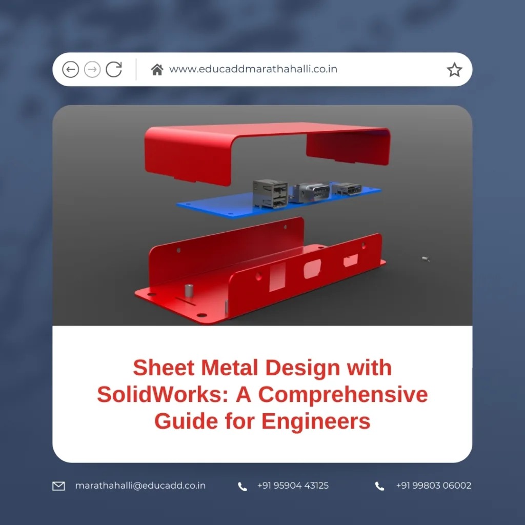
Sheet metal components form the backbone of modern manufacturing, appearing in industries such as automotive, aerospace, electronics, and industrial machinery. The ability to design sheet metal parts accurately and efficiently can save time, reduce material waste, and improve the overall quality of a product. SolidWorks, a leading CAD software, offers a complete suite of tools specifically tailored for SolidWorks Sheet Metal Design, from initial modeling to simulation and flattening for manufacturing.
SolidWorks Sheet Metal Design
In this guide, we explore everything engineers need to know about SolidWorks Sheet Metal Design, including design principles, practical modeling techniques, advanced features, simulation, and real-world applications. By the end of this guide, readers will understand how to create manufacturable sheet metal components that meet industry standards while optimizing workflow and productivity.
Understanding Sheet Metal Fundamentals
Designing sheet metal components begins with understanding the materials, manufacturing processes, and design considerations involved. Sheet metal is a thin, flat material that can be bent, cut, and formed into various shapes. Common metals used include stainless steel, aluminum, copper, and alloys, each with distinct properties that affect bending, stretching, and forming.
When designing sheet metal, several factors must be considered:
-
Material Thickness: Determines the stiffness and bendability of the part. Thicker materials require larger bend radii to avoid cracking.
-
Bend Allowance: The material stretches during bending. Calculating the correct bend allowance ensures the final part dimensions are accurate.
-
Grain Direction: Metals have a grain, and bending against the grain can lead to deformation or cracking.
-
Manufacturing Constraints: Punching, laser cutting, or stamping operations impose limits on feature size, bend radius, and hole spacing.
SolidWorks addresses these challenges by providing a Sheet Metal Module that incorporates bend tables, material properties, and automated calculations. This ensures that designs are both manufacturable and cost-effective.
Creating Sheet Metal Parts in SolidWorks
Creating sheet metal components in SolidWorks is structured and intuitive. The process typically starts with a base feature, usually a sheet metal flange. Users can specify parameters such as:
-
Sheet Thickness: Defines the overall thickness of the component.
-
Bend Radius: Sets the minimum radius to prevent cracking.
-
Corner Reliefs: Small cutouts at bends prevent tearing during forming.
Once the base feature is created, additional operations such as bends, hems, flanges, cuts, and punches can be applied. SolidWorks also allows engineers to convert existing solid models into sheet metal components, automatically identifying bends and edges for manufacturing.
The Flatten tool in SolidWorks is particularly valuable. It generates a flat pattern of the part, showing exactly how the material will be cut and bent. This reduces errors in production and enables precise collaboration with fabrication teams.
Practical Tip: Always start with the base flange in a logical orientation. A well-planned starting feature simplifies subsequent bends and cutouts while reducing rebuild errors.
Efficient Bend Management and Feature Control
Bends are the defining elements of sheet metal components, affecting both the shape and structural integrity of a part. SolidWorks provides robust tools to manage bends efficiently:
-
Automatic Bend Deduction: Calculates the material to remove for each bend to maintain accurate dimensions.
-
Neutral Axis Calculation: Adjusts the bend based on material behavior, ensuring correct final lengths.
-
K-Factor: Represents the ratio of material thickness to neutral axis location and influences bend allowance.
Feature control is equally important. Engineers can create cutouts, louvers, embosses, and other intricate designs while preserving the flat pattern. The parametric nature of SolidWorks ensures that if the base flange or bend is modified, all associated features update automatically.
Example: If a bracket requires a vent hole in a bent flange, adding the hole before flattening ensures the flat pattern accounts for stretching and bending. This avoids rework during manufacturing.
By carefully managing bends and features, engineers can reduce material waste, prevent assembly issues, and produce parts that meet design intent consistently.
Advanced Techniques and Best Practices
Advanced sheet metal design with SolidWorks leverages tools that streamline production, optimize material usage, and improve collaboration. Some key techniques include:
-
Multi-Body Parts: Create assemblies within a single part file. This is useful for complex enclosures or interlocking components.
-
Forming Tools: Predefined punches, embosses, and dies accelerate prototyping. Engineers can save custom tools for repeated use.
-
Configurations: Multiple design variants can be managed within the same file, ideal for parts with dimensional variations.
-
Design Tables: Excel-driven tables allow parametric control of multiple features, reducing errors in repeated designs.
Best Practices:
-
Maintain consistent bend radii across similar parts to simplify tooling.
-
Avoid sharp internal corners to reduce stress concentrations and improve forming.
-
Use the K-Factor and bend allowance calculations accurately for precise flat patterns.
-
Organize features logically, grouping similar bends and cuts to reduce rebuild errors.
-
Validate designs with manufacturing engineers to ensure feasibility before production.
These practices enhance efficiency, reduce trial-and-error, and improve collaboration between design and manufacturing teams.
Simulation and Validation
Simulation is critical in modern engineering to ensure designs meet structural and functional requirements before fabrication. SolidWorks Simulation enables engineers to test sheet metal components for:
-
Stress and Strain: Identify weak points in bends or flanges.
-
Thermal Effects: Ensure materials can withstand operating temperatures.
-
Deformation: Verify that bending or forming will not compromise the design.
-
Interference Checks: Confirm clearances in assemblies.
By combining simulation with parametric design, engineers can quickly iterate, optimizing thickness, bend radii, and feature placement. This reduces production delays and minimizes the risk of costly rework.
Practical Example: For a heat sink enclosure, engineers can simulate thermal expansion during operation. Adjustments to bend reliefs or flange dimensions can then be made virtually, ensuring both manufacturability and performance.
Real-World Applications
Sheet metal components are integral to countless industries:
-
Automotive: Chassis panels, brackets, heat shields, and body panels rely on precise sheet metal design for strength, weight, and assembly fit.
-
Aerospace: Aircraft fuselage panels, interior components, and structural brackets require lightweight yet durable designs.
-
Consumer Electronics: Enclosures, frames, and mounting brackets are often sheet metal for structural support and heat dissipation.
-
Industrial Machinery: Covers, brackets, and housings benefit from optimized sheet metal design for durability and ease of maintenance.
By mastering sheet metal design with SolidWorks, engineers can create components that meet exacting standards, reduce manufacturing costs, and improve product reliability. Integrating design, simulation, and manufacturing within a single platform streamlines workflows and enhances efficiency.
Conclusion
Designing sheet metal components requires a combination of material knowledge, design principles, and software expertise. SolidWorks provides a powerful environment for engineers to create, optimize, and validate sheet metal parts efficiently. By understanding fundamentals, leveraging advanced features, and following best practices, designers can produce high-quality, manufacturable components with minimal errors.
Whether designing automotive panels, aerospace structures, or industrial enclosures, adopting a structured approach to SolidWorks Sheet Metal Design ensures improved productivity, reduced costs, and better product outcomes.

